Skip to content
LEAP Australia Square Logo

Flownex simulation software at LEAP Australia

Flownex for Gas Turbines

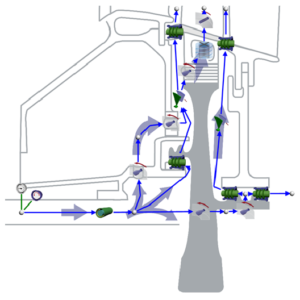
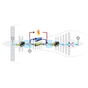
Optimise the preliminary design process by obtaining fast and accurate design results. Flownex® Simulation Environment is the perfect tool to model turbine secondary flow systems, combustion, flow and heat transfer.

Overview

Flownex® SE provides turbomachinery engineers with an easy to use, off-the-shelf tool for modelling combustion chambers, secondary air systems, blade cooling flows, lubrication systems with oil-air mixtures, as well as overall cycle integration and operation.

Secondary & Coolant Flows

Flownex®  includes a comprehensive rotating component library for analysing the secondary air system of a gas turbine engine. This enables engineers to quantify the bleed air consumption and flow distribution through the entire system. Furthermore, coupling Flownex® with Ansys Mechanical enables engineers to perform detailed thermal studies of critical rotating components. Flownex® includes:

  • Real gas models
  • Windage power calculation
  • Choking calculations
  • User-defined HTCs


SECONDARY FLOW

Flownex 2D fluid simulation for Gas Turbines at LEAP Australia

BLADE COOLING

By coupling 1D flow Flownex® models with 3D heat transfer models in ANSYS Mechanical or CFX, a detailed turbine blade cooling simulation can be conducted. Flownex® contains industry-standard pressure drop and heat transfer correlations for typical turbine blade features such as turbulator strips and pedestals. This allows designers to rapidly see the effects of their design changes on the maximum blade temperatures and cooling airflow rate.

Flownex 2D fluid simulation for Gas Turbines at LEAP Australia

Lubrication System

The primary use of Flownex®  in lubrication systems is used to determine optimum drain line sizes given the limited space inside the engine. This requires two-phase pressure drop calculations in lines with oil-air mixtures. In parallel with this engineers can determine whether or not scavenge pumps are required for fluid transportation in the drain lines and, if so, what the pumping requirement will be.

Flownex 2D fluid simulation for Gas Turbines at LEAP Australia


Combustion Chamber

Preliminary combustor design requires that an extensive number of geometrical and operational conditions be evaluated and compared. Especially during this phase, Flownex® is an essential tool for combustor design engineers as it accurately captures important parameters such as the mass flow rate distribution through air admission holes,
associated pressure losses as well as liner wall temperatures.

Flownex 2D fluid simulation for Gas Turbines at LEAP Australia

Experimental Comparison

A comparison to experimental data published by NASA shows good agreement between the Flownex® results and real-world temperatures of the liner wall for a wide range of operating conditions. The full report was presented at the 2016 ASME turbo expo.

Flownex 2D fluid simulation for Gas Turbines at LEAP Australia

Integrated System Analysis

Flownex® allows engineers to couple all turbine models (combustor, secondary flow, and lubrication) with the main flow path to understand the performance of the entire engine.

Flownex 2D fluid simulation for Gas Turbines at LEAP Australia

Want to learn more about Flownex solutions for Gas Turbines?

Complete the form and our team will contact you to discuss your needs.