Previously
In the first entry in this series, we explored the creation of a multifunction radar in Ansys STK, to model the realistic detection of an aircraft based on factors including radar cross section, flight behaviour and more.

Figure 1: Patrol Boat with Multifunction radar from Part 1 in this series
This Time – Intercept Aircraft
In this entry, the DRM is expanded to include an intercept aircraft, to be launched if/when the radar’s PDet (Probability of Detection) exceeds a certain user defined threshold. At this point in the time, the interceptor shall execute a rendezvous with the target aircraft, before returning to the airstrip a short time later.
Aircraft definition
To define a physics accurate aircraft model, we have employed STK’s “Aviator” tool for this DRM (Design Reference Mission). This tool enables the definition of an aircraft model, including selection from a number of pre-installed options within STK. In this instance, the “basic fighter” option has been employed, with some slight alternations made to some of the aerodynamic data. For example, the “basic fixed wing” strategy is selected to define the aircraft’s aerodynamic characteristics. This includes information such as coefficients of lift, drag and min/max angles of attack. Combined, this will ensure any manoeuvres attempted by the aircraft are done so in line with the aircraft’s real-world capabilities.

Figure 2: Unidentified Target Aircraft Passing over Patrol Boat
Flight path planning
Using STK’s “Analysis Workbench” tools, the aircraft is programmed to take off from a nearby airport if/when the radar PDet exceeds a user defined threshold. In doing so, the interceptor will automatically adapt to any simulation changes later in the project. This might include performance models or aircraft specs for the interceptor itself, altered radar specifications facilitating better/worse detection, and any variation of flight path by the target aircraft.

Figure 3: 2D view within STK showing Interceptor (yellow) approaching target aircraft (red)
This ensures the user can rapidly test a broad scope of use cases, and immediately assess the quantitative and qualitative effects these changes impose on the mission. For example, we can monitor the fuel consumption of the interceptor aircraft throughout its flight, comparing various aircraft performance models, payloads, and rendezvous routes. Very quickly, this allows us to develop an understanding of the capabilities and limitations of our system.

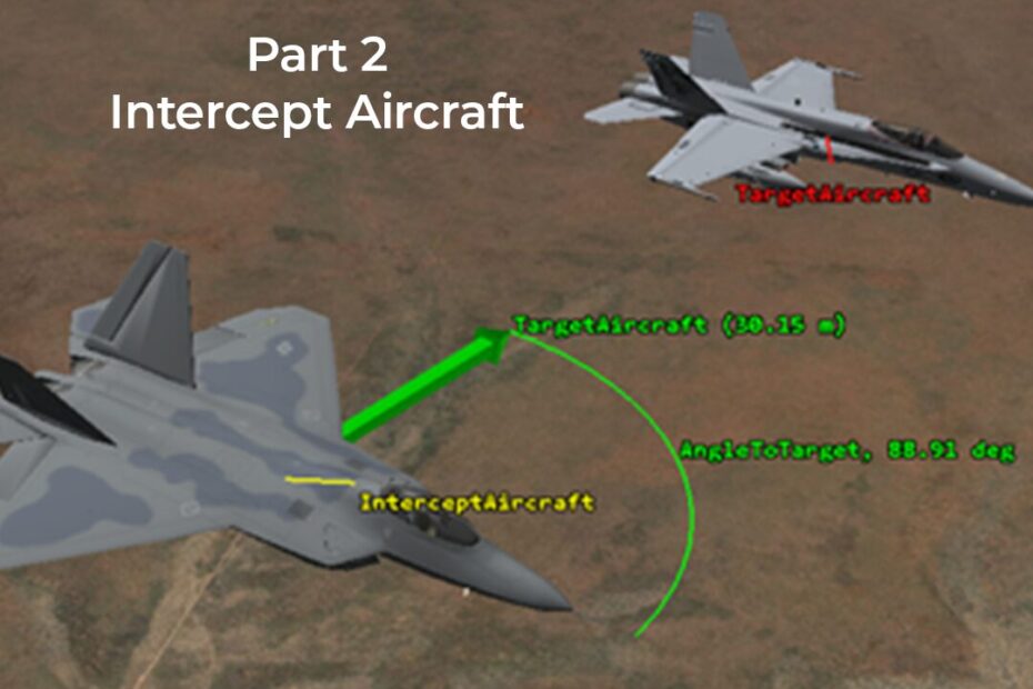
Figure 4: Interceptor alongside target aircraft with green vector showing both the angle to the target craft, as well as the distance between the two
Next Time
With the aircraft portion of the DRM complete, the crucial element of communication between assets remains unclear in the current configuration. Join us in part 3 of this series for the final element of this DRM – a LEO constellation and communication link between multiple moving assets across the mission we’ve defined so far.

