Skip to content

Water Treatment

Design & simulation solutions for water treatment.

Filtration, sedimentation, flocculation, aeration and chemical or UV dosing: the water we consume goes through these processes between the source and our household taps. Our simulation tools are used by clients all across Australia to provide the nation with clean potable water. 

Chlorine dosing for water treatment

Engineers need to know how effectively the given amount of dosage mixes with the water stream. They also need to understand if there are regions of recirculation and what the concentration of dosage is at N diameters downstream of the inlet.

Most of the equipment are either too big to continuously build and test or it is near impossible to replicate the exact test conditions. Furthermore, CFD inherently provides a full picture of the entire 3D space in one-go. While solving for dosage concentration, it also provides detailed information on the velocity field, settling, temperature and pressure.

Watch our short video examples to learn more:
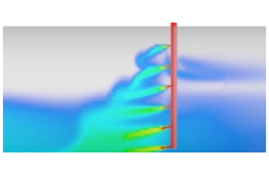
Simulating chlorination of Untreated Water

Chlorination of Untreated Water

CFD was used to determine the location & number of chlorine jets to achieve a CoV concentration at a desired location within the pipework.
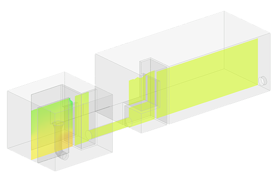
Simulating water treatment problems

Saving $50k from 48hrs of CFD

Simulation provided an easier route to achieving design objectives without the purchase of new equipment or time consuming experimental tests.

Water Hammer within flow networks

Near instantaneous shut offs of a valve or unexpected breakdowns in equipment cause a spike in loads. These unexpected loads, like water hammer or surge can compromise the structural integrity of the pipe work and cause even more catastrophic damage.

Engineers need to understand what the flow field looks like before, during and after the shut down, so that enough mitigative measures can be put in place to protect equipment

Most of the time, such analyses can be done via a system level tool, without having to go to full 3D CFD. This means the entire network can be setup in less than an hour + results obtained in seconds or minutes after. Implicitly this allows hydraulic engineers to assess a multitude of scenarios and designs on-the-fly

Equipment sizing for flow straightening, pressure drops, mixing, turbomachinery and more…

Engineers who want to manipulate the flow field quite often need equipment placed in the flowstream, to alter the flow’s behaviour. This however requires an understanding of the equipment itself (pressure loss through a filter, or pressure drop through guide vanes, for example). Such a task usually also requires understanding how many pieces of said equipment is required, how big should it be and which one from a supplier list, best suits the nominal operating conditions.

Modelling the details of an equipment or representing it via a black-box approach within a large network helps engineers tweak the flow parameters, to achieve the behaviour they want.

Want to learn more about Ansys simulation solutions?

Complete the form and one of the experts from our Ansys team will contact you to discuss your needs.

LEAP Australia - Ansys Elite Channel Partner in Australia and New Zealand