
Ansys Sherlock is a reliability tool for electronics components that allows engineers to make fast and accurate life predictions for their electronics hardware.
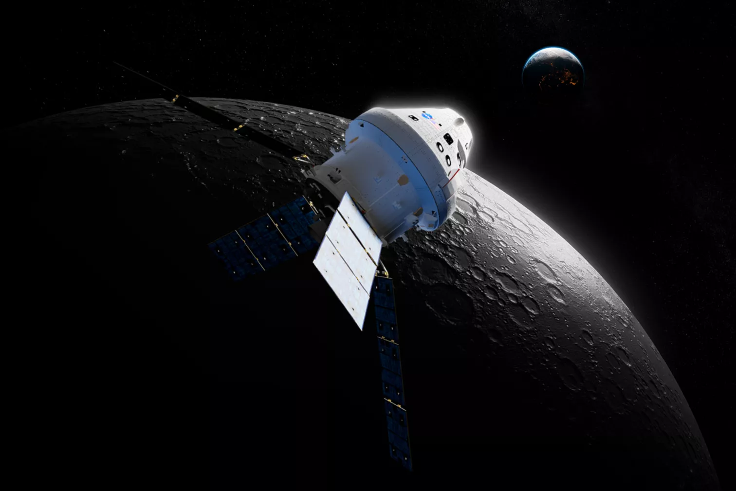
This post will give a high-level overview of using Sherlock to examine a mission-critical PCB onboard a spacecraft. This PCB is part of a module expected to make multiple trips out into orbit and then back to Earth.
To ensure the reliability of this PCB, we’ll use Ansys Sherlock to simulate launch and re-entry conditions. We expect this module to have a service life of five years, where the module is experiencing three mission trips per year. We’ll set our reliability goal at no more than a 5% chance of failure over the service life of the PCB.
The first phase of our PCB’s life will be launch. We’re going to simulate launch conditions with three events, a shock event, a random vibration event, and a thermal event. From MIL-STD-810H, we’ll estimate the shock experienced by the PCB with a mid-field mechanical shock of 1000G across 10ms.
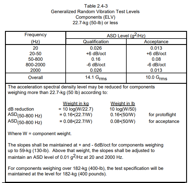
For the random vibration component, we’ll use the NASA GSFC standard 7000A, the general environmental verification standard for flight programs and projects. Table 2.4-3 from this standard gives us a guide for the random vibration profile we should be testing our PCB with. A modal damping ratio of 0.03 is applied.
Finally, we’ll also consider a thermal event during launch. The module will start at 0˚C, go up to 60˚C as the module exits the atmosphere, and then drop -20˚C, occurring during rapid depressurisation as the module exits the atmosphere. This will be modelled with two temperature events, a heat-up phase and a cool-down phase.
Once the PCB has successfully been launched into space, the next phase of life will be re-entry. We’ll use the same random vibration event from the 7000A NASA standard, but this time our temperature profile will start at 0˚C, go to 70˚C during re-entry, and cool back to 0˚C. Finally, another MIL-STD-810H shock event will occur on landing.
Setting up the PCB Lifecycle:
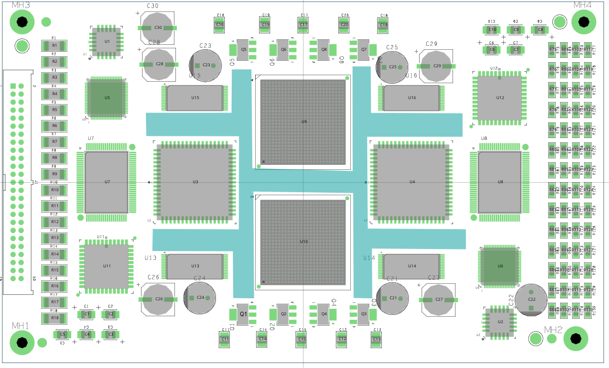
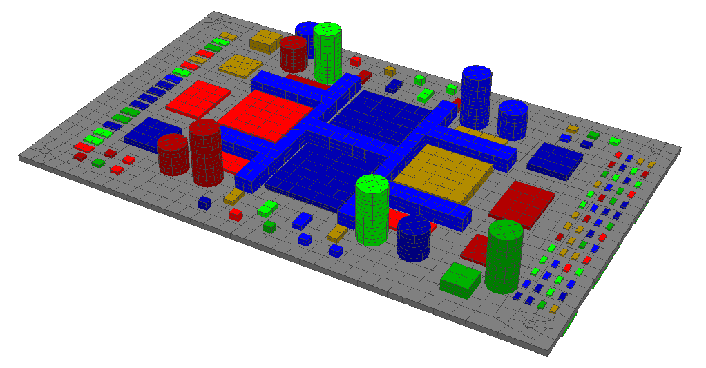
First, we import our ODB which could have been produced by any major ECAD software, such as Altium, Cadence, Mentor Graphics, KiCad, Eagle etc. For this example, we are going to use the sample ODB included with the Sherlock installation, with added mechanical stiffening frames. Ansys Sherlock comes with a library of over 600,000 electronic parts, so setting a model of your PCB is easy and efficient.
We are going to enable ball grid array modelling using the two-element model for the BGA components on the board, labelled U9 and U10. We are particularly concerned about the fatigue in these parts due to their large footprint and central location. The solder type used for this board is going to be SAC305.
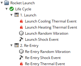
Using Ansys Sherlock, it’s easy to setup multiple events across different phases of an electronics lifecycle. Using the event descriptions above we can create a lifecycle for our PCB board.
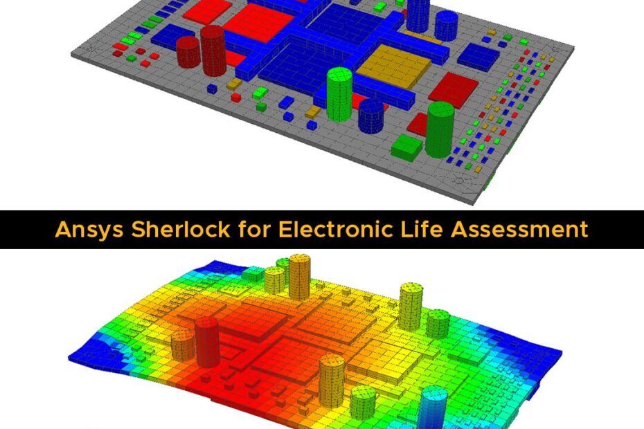
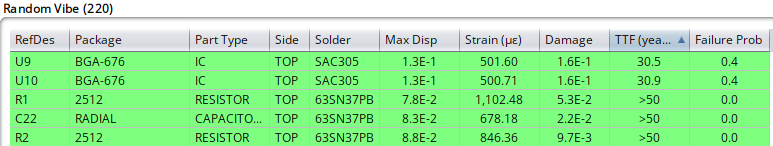
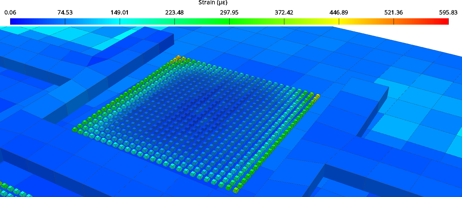
Ansys Sherlock will perform FEA simulations and analyse the stress and strain histories to evaluate the effective damage and life of components. From the random vibration events, we can see that our BGA components are the most damaged, but each component has a time-to-failure of roughly 30 years.
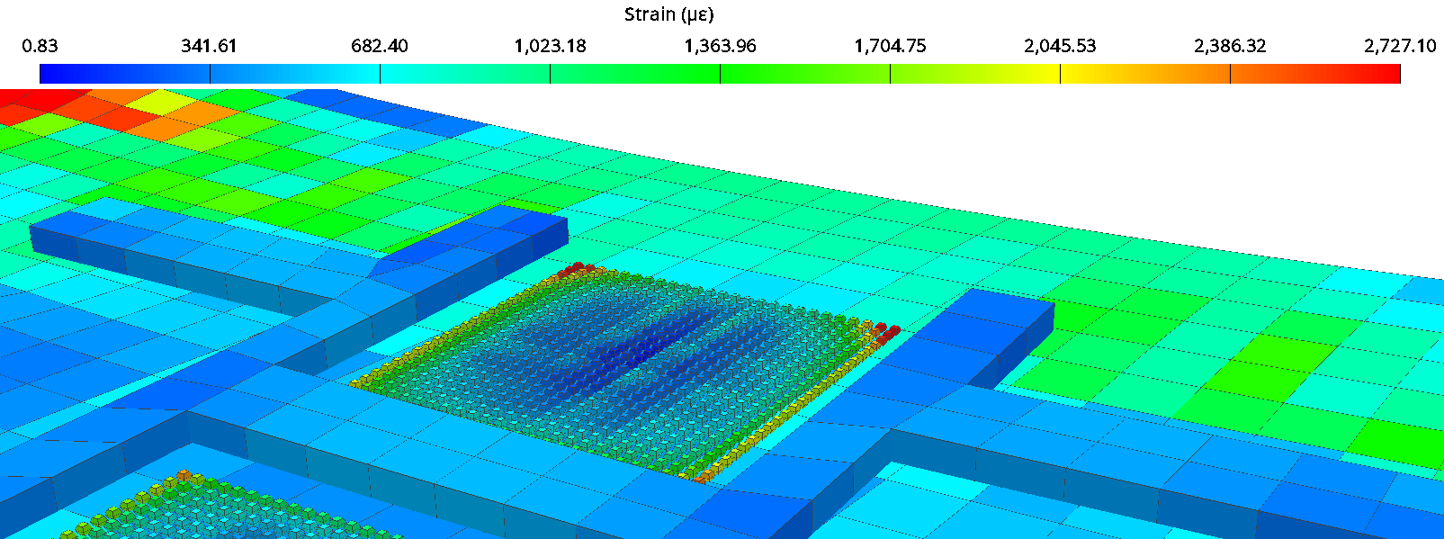
Using the 3D model, we can examine the stress and strains in the solder balls attached to U9 and U10. The solder balls on the corners of our BGA are subject to high strains, and so to improve the lifespan of our PCB we could consider design changes to minimise strains on the BGA components.
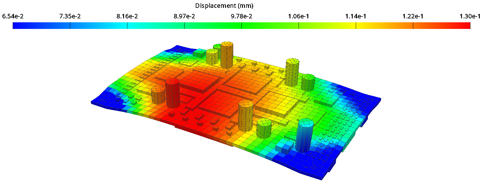
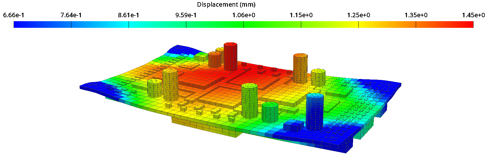
The shock results reveal a similar story, with component U9 being subject to the largest displacements on the board, causing the corner solder balls to be highly stressed.
Ansys Sherlock utilizes Lusser’s Law to calculate system-level probabilities of failure from individual component probabilities. These are then graphically combined, providing engineers with an immediate visual representation of the expected failure rate over the board’s lifetime.
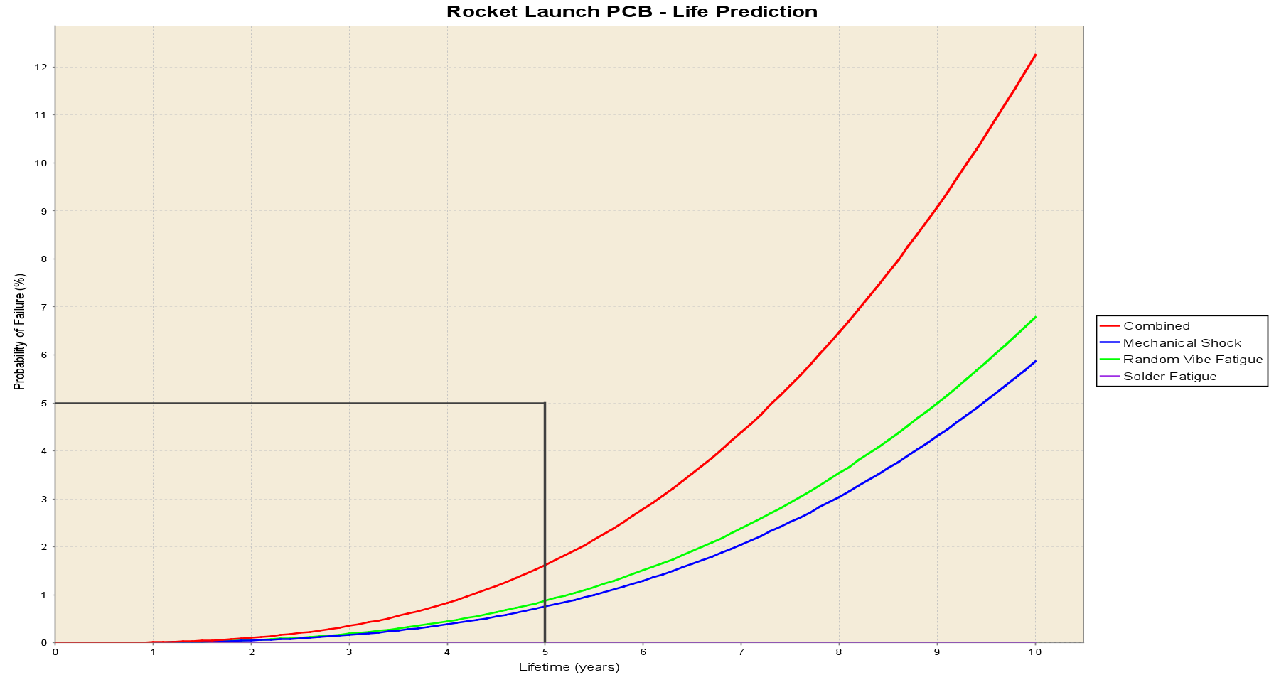
The results clearly demonstrate that the board meets the requirement of a maximum 5% failure rate over five years. Mechanical shock and random vibration events are the primary contributors to the failure rate, while thermal events (via solder fatigue) play a comparatively minor role in determining the system’s lifetime in this specific example.
Next steps?
Are you ready to replicate this workflow for your own PCB design project? Reach out to LEAP’s expert team to learn more about Ansys Sherlock for improved electronics reliability.