Guest Blog by Dr Daniel Grasser, Consulting Engineer at TUNRA Bulk Solids, Newcastle (Australia). In this blog, Daniel introduces guidelines for the Discrete Element Method calibration in the context of bulk solids handling and mining/minerals which he expanded upon in our webinar Materials Calibration for DEM Simulation of Bulk Solids – Watch on-demand
Predicting the bulk solid’s behaviour and extracting information which cannot easily be measured experimentally are key benefits of Discrete Element Method (DEM) simulations, such as Ansys Rocky DEM. However, the quality of the prediction depends on the calibration of the simulation. Surely, modern simulation software is user friendly, and most engineers can set up a DEM simulation within a short time, but does this mean that outcomes are meaningful?
Meaningful DEM results require best-practice calibrations and an understanding of the different flow regimes of bulk solids. To achieve this, the following article aims to be a guideline for engineers.
Introduction
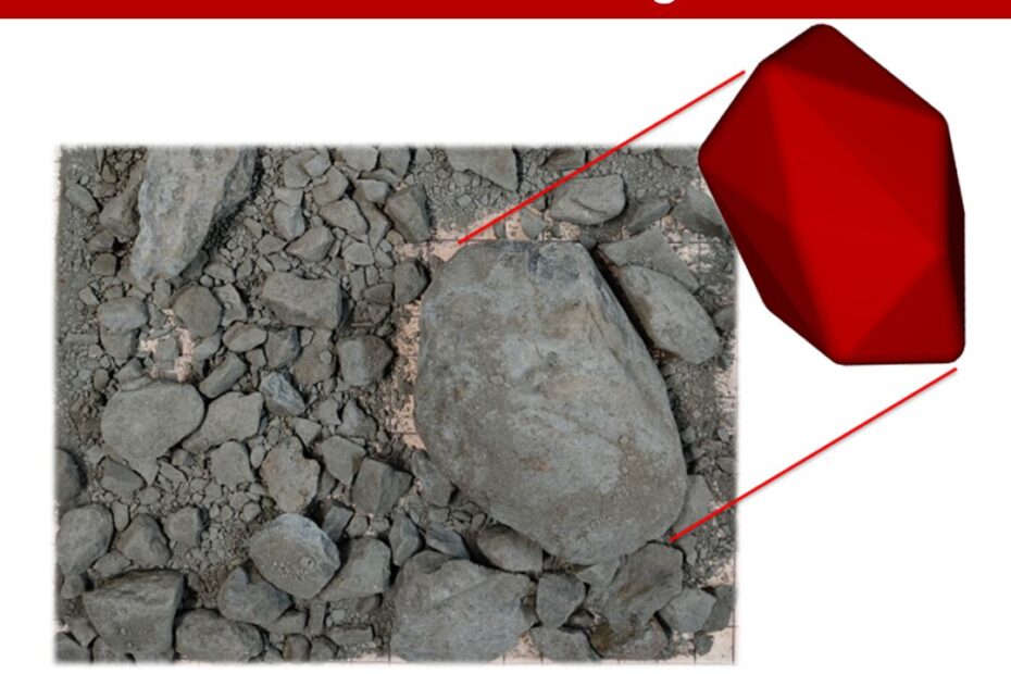
As the “Discrete” in Discrete Element Method indicates, each particle is modelled individually. However, most industrial applications involving bulk solids consist of large numbers of individual particles. This requires an upscaling of the particles and an approximation of the particle shape to reduce the computational efforts. As a guideline, the larger the particle size, the higher the importance of implementing a realistic particle shape. For example, the large particle in Figure 1 (left) should be implemented in a good approximation of the shape and size. On the other hand, the fines in Figure 1 (right) can be implemented as spherical particles for most applications.
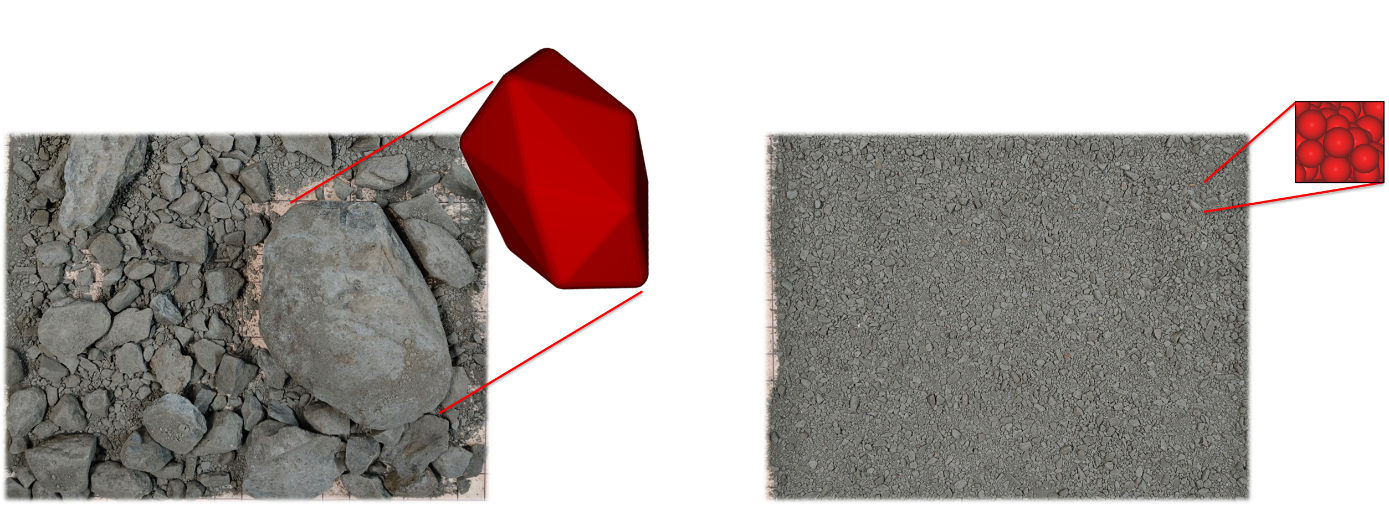
Figure 1: Particles and their implementation in Rocky DEM. Left: sphero-polyhedron for large particles, right: spheres for small particles
For the application of DEM as a predictive tool, a comprehensive set of thoroughly conducted independent calibration tests is required. Each test represents a specific flow regime, such as particle-particle, particle-wall, and static and dynamic conditions. Figure 2 illustrates examples of DEM calibration tests for these regimes.
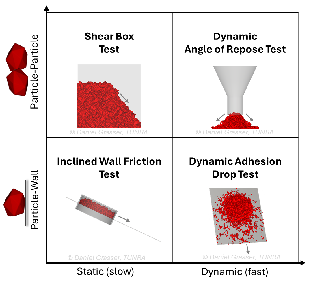
Figure 2: Examples of DEM calibration tests used in the context of bulk materials handling and mining.
The following passage explains each flow regime and provides examples of the corresponding tests.
Shear Box Test
The Shear Box Test consists of a cubical box with a side wall that are rapidly removed. After the side wall has been removed, the material slumps over itself and the angle of the resulting shear plane can be measured. In the Shear Box Test, the friction and cohesion between the particles can be adjusted until the shear angle matches the experimental result. Overall, the Shear Box Test is governed by particle-particle interactions at relatively slow velocities under low consolidation pressure.
Angle of Repose Test
The Angle of Repose Test can be conducted as a static or dynamic test. In both tests, the angle of repose is formed by a conical pile of bulk material discharged from a funnel or pipe (Figure 3). For the static case, a quasi-static choked flow is retained. For the dynamic case, the conical pile is created by dynamically discharging the material. Depending on the targeted calibration, the bulk material can be unloaded on a wall liner or a bed of bulk material. The Angle of Repose Test often is used as an indicative comparison between bulk materials under quasi-static or dynamic flow regimes.
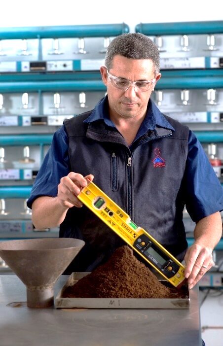
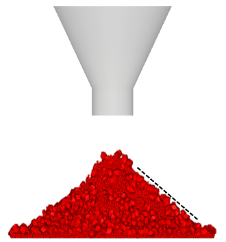
Figure 3: Angle of Repose Test. Left: experiment, right: Rocky DEM simulation.
Inclined Wall Friction Test
The Inclined Wall Friction Test is applied to calibrate the friction and adhesion parameters between an inclining wall and the bulk material under quasi-static conditions (Figure 4). Using the particle-particle parameters which previously have been calibrated in the Shear Box Test, the particle-wall friction is adjusted until the slip angle matches the experimental results. Depending on the application, the bulk material can be loosely placed on the wall liner or inside a cell with a consolidation pressure applied. Moreover, adhesion models can be applied to capture the effect of the consolidation pressure on the wall friction angle. Overall, the Inclined Wall friction Test can represent particle-wall interactions under a quasi-static regime for a wide range of consolidation pressures.
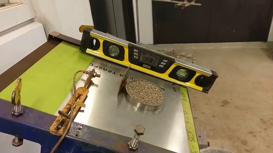
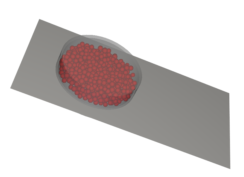
Figure 4: Inclined Wall Friction Test. Left: experiment, right: Rocky DEM simulation.
Dynamic Adhesion Drop Test
The Dynamic Adhesion Drop Test is used to calibrate the adhesion between the bulk material and wall under dynamic conditions. The bulk material is discharged from a horizontal conveyor belt on a set of wall liners which are inclined at different angles. The adhesive parameters of the DEM model are adjusted until outline of the accumulated bulk material and amount of material are matching the experimental results. Hence, the Dynamic Adhesion Drop Test is an important test for the calibration of the adhesive behaviour between particles and wall under a dynamic flow regime.
Wear Calibration Test
In addition to calibrating particle-particle and particle-wall interactions, wear calibration tests can be conducted (Figure 5). Generally, the wear process of wall liners which mainly wear due to abrasion can be modelled using Archard’s wear law. However, this excludes impact wear due to fracture. A modelling parameter termed Volume/ Shear Work ratio needs to be calibrated to represent the wear rate of the wall liner. The wear constant is often accelerated by several orders of magnitude, for example, seconds in the DEM simulation represent hours in the experiment (Figure 5). Once calibrated, the simulation can predict the wear volume of a wall liner resulting from shear work (sliding distance · sliding force) induced by the particles. Wear modelling can predict the service life of equipment and is especially useful when changes in the surface shape of the equipment are of interest.
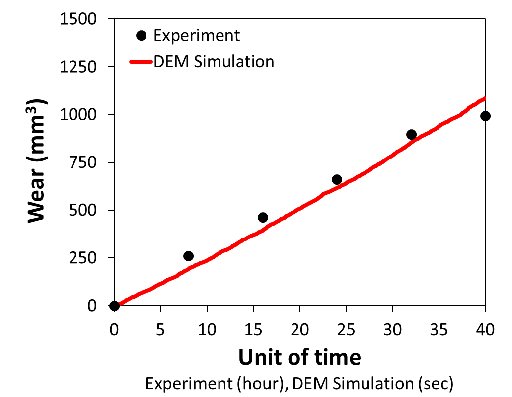
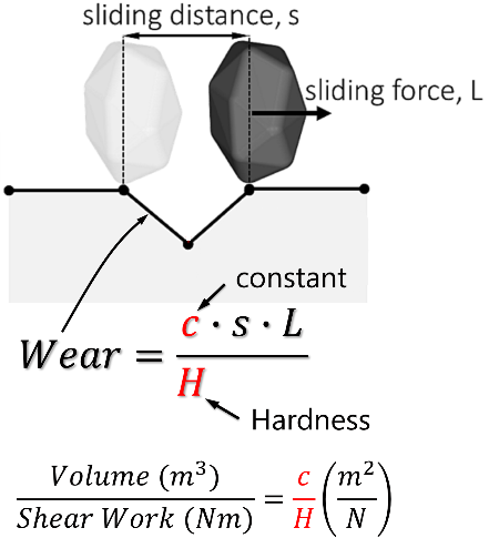
Figure 5: Wear calibration. Left: experimental and DEM simulation result, right: Archard’s wear model implemented in Rocky DEM.
Getting Started with DEM – Watch webinar on-demand
Discrete Element Method (DEM) simulations are suitable to predict the bulk solid’s behaviour. However, it is necessary to calibrate and experimentally validate the simulations with a set of tests that represent a comprehensive set of flow regimes. In addition, the abrasive wear of equipment can be predicted when the model is calibrated based on experimentally obtained wear rates. Dr. Daniel Grasser from TUNRA presented a joint webinar, hosted by LEAP Australia to discuss the important topic of materials calibration for DEM simulation of bulk solids- click the image to watch on-demand.
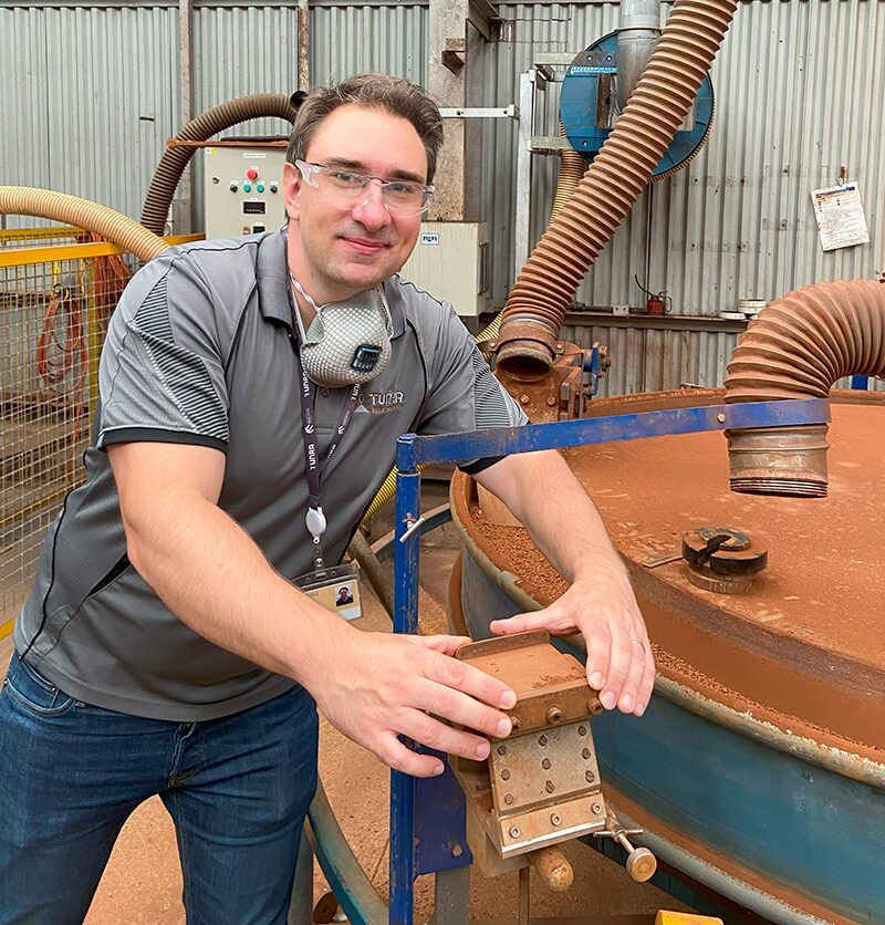
About the Author: Dr. Daniel Grasser, Consulting Engineer, TUNRA Bulk Solids
Dr Daniel Grasser is a mechanical engineer with interests in bulk materials and resulting wear. Daniel obtained a PhD from the Institute for Frontier Materials (IFM), Australia, and was then appointed as an Associate Research Fellow, working in the field of wear testing of metals. In 2023, Daniel joined TUNRA Bulk Solids as a Consulting Engineer. He is particularly interested in addressing issues related to wear of mining equipment resulting from abrading and impacting solid particles. Daniel employs experiments and numerical simulations, including the Discrete Element Method.