
Today’s engineering teams face unrelenting demands: shorter development cycles, tougher performance targets, lower costs, and stricter safety and environmental requirements. Products that were once designed by hand and validated through simple analytical calculations have now become the result of many competing objectives evaluated across large, multidimensional design spaces.
The only way to win in this environment is to do more design exploration – faster, and to make decisions based on systematic, data-driven insight rather subjective judgment.
Modern day Computer-Aided Engineering (CAE) has progressed to become the backbone of product design, development, and life-cycle management. A typical CAE-driven workflow might look like the following:
Within this process, engineers and product designers will grapple with multiple inter-related steps:
Concept and CAD
Engineers create a baseline geometry in a CAD system. Early design intent, packaging and interfaces are defined here.
Geometry preparation and parameterisation
Geometry is cleaned up, defeatured and parameterised. Key dimensions, thicknesses or shape-control parameters are exposed for study.
Meshing and model setup
The geometry is meshed, and physics are specified (materials, boundary conditions, loads, contacts, solver settings).
Simulation execution
A solver (structural FEA, CFD, thermal, multiphysics, crash, NVH, etc.) runs the model — often on local clusters or HPC. Each run can take from minutes to days.
Postprocessing and validation
Results are reviewed, key metrics extracted, and the model is validated against tests or previous data.
Decision and iteration
Based on results, engineers modify the design, adjust parameters, or refine the model and repeat.
This iterative loop of model, run, review, and redesign is repeated many times by the user, in isolation. For complex products it becomes a bottleneck of manual tasks, i.e. re-meshing after a CAD tweak, re-applying boundary conditions, tuning solver/physics model parameters, scripting postprocessing to extract the same metrics, and chasing down convergence or fidelity issues.
As a result of this, traditional CAE workflows inherit some common pain points, which can significantly hinder productivity. These can be experienced irrespective of the application/industry.
Manual/laborious and error-prone setup:
Much time is spent preparing geometry and ensuring consistent solver inputs across dozens or hundreds of cases.
Long run-times and resource contention:
High-fidelity simulations are expensive; waiting for queue times means lost momentum.
Fragmented toolchains:
CAD, meshers, solvers, pre/postprocessors, PLM and results repositories are often disconnected, causing friction and data translation errors.
Limited design exploration:
Because each simulation is costly, engineers only sample a tiny fraction of the design space, risking missed opportunities.
Bottlenecks around expertise:
Most organisations have many designers but only a few simulation experts and limited compute capacity, creating queues and long iteration times.
Optimisation workflows often require specialists in scripting, DOE, surrogate modelling or topology optimisation — skills that aren’t uniformly available across teams.
Decision and iteration
Based on results, engineers modify the design, adjust parameters, or refine the model and repeat.
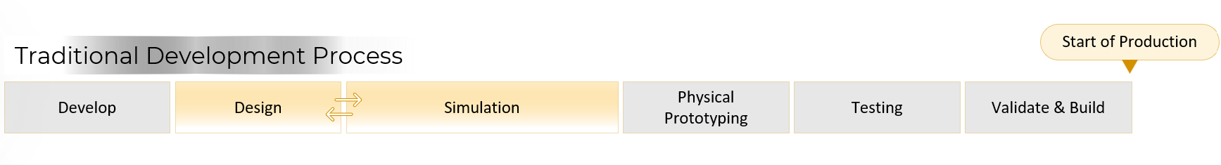
Each of these factors contribute to developing environments where missed opportunities are pervasive early on in the product development cycle. Simulations are often employed late (detailed modelling, prototyping, testing) rather than during conceptual and preliminary phases – where design freedom is highest and changes are the cheapest. Skipping early exploration through simulation forfeits the opportunity to obtain critical knowledge about how geometric features and operating conditions drive responses/behaviours of interest.
At its core, the key pressures lie between accelerating development and ensuring reliability, all while balancing cost control and flexibility to innovate. Since engineers are under constant pressure to deliver faster, safer, and more cost-effective designs, we need a way to evaluate trade-offs ‑early, before design freedom is lost. Ansys OptiSLang is built precisely for this purpose, by changing the paradigm from “simulate to check” to “simulate to discover”.
Think of OptiSLang not as a single solver, but instead as a tool used to wrap around and manage the existing CAE loop – automating the hard parts and extending capability. OptiSLang integrates directly with CAD, Ansys, and other simulation tools to automate the processes of parameter variation, Design of Experiments (DOE), sensitivity analysis, and optimisation. Instead of manually running hundreds of cases, engineers now only need to define parameters and objectives once. OptiSLang then drives the simulations, interprets the results, and guides users toward the most influential design factors and best-performing variants.
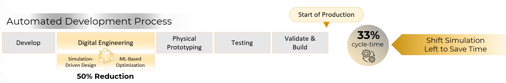
Now, rather than running isolated analyses to check performance after-the-fact, OptiSLang standardises and automates these workflows within your Digital Engineering phase, transforming the simulation process to include:
- Process automation: Seamlessly link CAD, meshers, solvers, and postprocessing steps into a repeatable, automated workflow.
- Sensitivity and robustness analysis: Understand which parameters matter most and how uncertainty in those inputs affects performance.
- Optimisation and trade-off exploration: Use built-in or custom algorithms to balance conflicting goals — weight vs. stiffness, performance vs. cost, and more.
- Data-driven decision making: Replace guesswork with insight derived from statistical analysis and visualisation of the entire design space.
Helping CAE teams shift from reactive model checking to proactive, knowledge-driven design exploration, OptiSLang puts consistent, interpretable data directly into the hands of the people who need it the most:
- Design engineers, who can rapidly test “what-if” ideas and explore design sensitivities without waiting in solver queues.
- Project leads and decision-makers, who can visualise trade-offs across competing objectives and drive design strategy with confidence.
- Simulation specialists, who can automate repetitive workflows and standardise best practices across teams.
The result is faster iteration, fewer prototypes, and higher design confidence — all without requiring every engineer to be an expert in these optimisation methods!
With OptiSLang orchestrating the existing CAE toolchain, the same models and solvers you already use become part of an intelligent, iterative loop that continuously learns from results. The output isn’t just a successful simulation its tangible knowledge delivered at the point of highest value in the development process – when design choices are still flexible and the cost of change is minimal.
If you would like to learn more about how OptiSLang can improve your simulation workflow, reach out to our team today to arrange a chat.