Applying Tangential Pressure in Ansys Mechanical – Transfer Chutes
In this post we’ll demonstrate a variety of ways to apply tangential pressures to surfaces in Ansys Mechanical, through the lens of transfer chutes. Transfer chutes are very commonly used in bulk material processing and handling scenarios, particularly for bulk granular materials. The same process is also relevant for simulating a range of similar situations, such as silos, hoppers, or brake pads.
When analysing the structural performance of a transfer chute, it’s important to consider how the flow of material will impact your design, and to then quickly evaluate the structural performance of the design under load.
Whilst it’s straightforward to account for the normal component of pressure in a design, the tangential pressure is a trickier load to setup. In this blog, we’ll investigate how you can setup pressure loads to capture tangential pressures for a variety of transfer chute geometries.
Rectangular Constant Cross-Sections
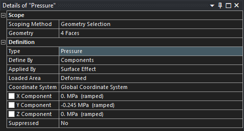
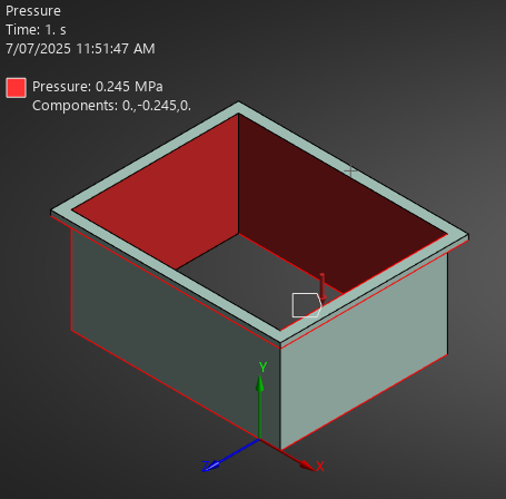
One of the simplest transfer chute geometries to consider is the rectangular constant cross-section geometry. These are especially simple in Ansys Mechanical if the path of the transfer chute aligns with a global cartesian axis. In this case a standard pressure condition can be scoped to the surfaces you want to apply tangential pressure to. Once scoped, simply define the pressure condition via components, and use the axis tangential to the selected surfaces.
A rectangular transfer chute, with faces aligned with the global Y-cartesian axis. A tangential pressure of -0.245 MPa is applied to the interior faces in the global negative Y direction.
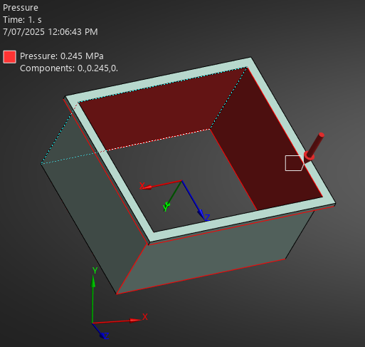
If the transfer chute isn’t nicely aligned with any global axis, we can insert a local coordinate system with axes aligned to our geometry, then follow the same process as above.
The rectangular transfer chute now points in an arbitrary global direction. A new local coordinate system is defined based on geometry, and a tangential pressure of -0.245 MPa is applied to the interior faces in the local Y direction.
Conical Cross-Sections
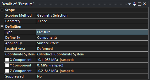
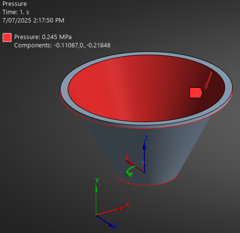
A conical surface is a good example of a geometry where defining a constant tangential pressure is not straightforward in a cartesian system. Luckily, this is still very straightforward to implement in Ansys Mechanical via local cylindrical coordinate systems.
The conical cross-section matches this type of coordinate system, allowing us to apply the tangential pressure with a single pressure object. Using the cylindrical coordinate system, X is the radial direction, Y is the theta direction, and Z is the vertical direction. Scoping the coordinate system to the outlet of our chute, we can use a bit of trigonometry and the angle of the cone to decompose our 0.245 MPa tangential pressure load into cylindrical components X and Z.
A conical transfer chute with a cylindrical coordinate system at its base. A tangential pressure load can be applied using the cylindircal coordinate system and some trigonmetry.
Complex Geometry and Pressure Loads
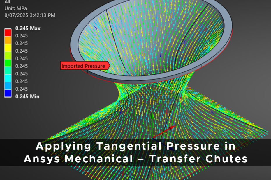
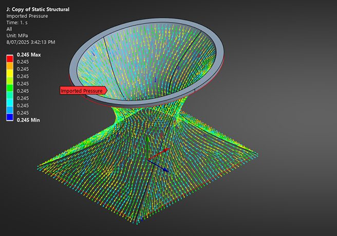
More complex geometries often will have no simple axis or coordinate system to define a tangential pressure. In this case, tangential pressures can be imported onto the surface.
For complex transfer chute geometries, often no single coordinate system or axis can be defined that would enable us to create a tangential pressure object. In this scenario we can use a .csv file to import tangential pressure loads onto surfaces of arbitrary complexity.
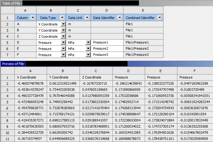
First, you must create a .csv file which contains a point cloud of pressures versus coordinates. For this example, we used Mechanical scripting to export the element centroids of a mesh, along with pressure values simulating an arbitrary bulk material flow through the chute that causes a constant tangential pressure of 0.245 MPa. Here, we could also have used Ansys Rocky to simulate the flow of granular material through the transfer chute and then imported the results into Ansys Mechanical to evaluate the structural response of the design. The integration between Ansys Rocky and Ansys Mechanical is discussed more here.
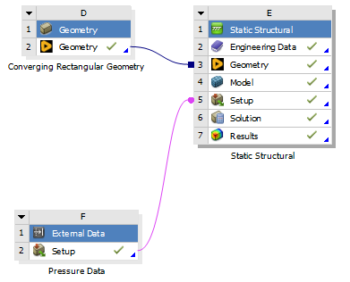
The .csv file can be read into Ansys Workbench via an External Data field and connected to our analysis.
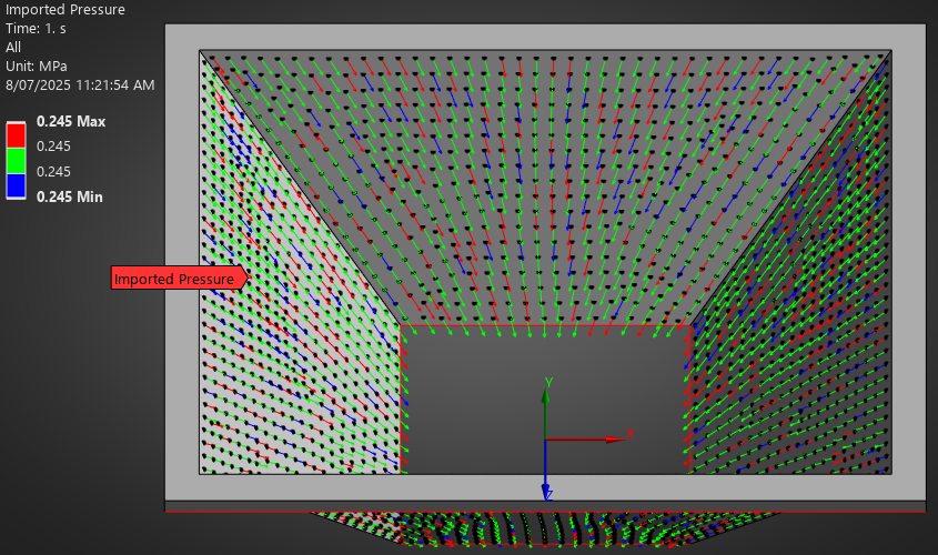
Inside of Mechanical, this will create an Imported Load object, which you can specify as a pressure load. Mechanical will then read in the point cloud specified by the .csv, which can be visualised to ensure that the direction and magnitude of the pressure vectors is correct.
Using the above methods, you can accurately simulate the tangential pressure in many scenarios, ranging from transfer chutes, machine tool interactions, brake pads, seismic isolators, and many more. Talk to LEAP for advice on how best to simulate tangential pressure in your next project.