In our previous blog post, we demonstrated Ansys Discovery’s impressive performance when modelling plate-like structures. However, real-world construction involves a wide variety of structures, many of which are much more complex than simple plates. For this reason, the NAFEMS benchmarks features a range of 3D structures, ensuring that the FEA software can accurately handle a broad spectrum of geometries. Ansys Discovery rises to this challenge, delivering precise results even with as we progress to more complex 3D geometries.
LE2 – A Cylindrical Shell Patch

Grain silos demonstrate exactly where one could expect to find cylindrical shell structures. (Source: Geograph)
While this NAFEMS test is only designed to model a small section, it is a good test of Discovery’s ability to accurately model a very common shape: cylinders. Cylindrical shells are frequently used across many engineering disciplines, from civil infrastructure to pressure vessels, making them relevant to nearly every industry.
Modelling cylindrical shells, especially when they’re part of larger assemblies, can be quite challenging. While this is typically done with shell elements, in this instance we have modelled the cylindrical section using solid elements in Discovery. This approach brings real advantages when it comes to accurately representing the connections between cylindrical shells and components such as ring stiffeners, endcaps, or foundations. By utilising solid elements, Discovery delivers precise stress results at critical connection areas, giving you a clear and reliable understanding of the true behaviour of these structures.
What are the unique features of NAFEMS LE2?
This benchmark allows us to investigate Discovery’s performance in analysing thin, curved shells subjected to bending. The cylindrical shell patch is 0.01 metres thick and is fixed along one axial edge, as shown in the schematic below. Symmetry conditions are applied along both radial edges.
The setup involves two load cases. For the first load case, a uniform edge moment of 1 kNm/m is applied along the axial edge opposite the fixed support. In the second load case, an outward normal pressure of 0.6 MPa is applied to the outer cylindrical face, along with a 60 MPa outward normal pressure along the same axial edge as before. For both the load cases, the expected tangential stress at point E on the outer surface of the cylinder is 60 MPa.


FEA schematic for LE2, taken from The Standard NAFEMS Benchmarks
How are we setting this up in Discovery Explore?
For both load cases, edge AB was fixed in all degrees of freedom, while symmetry conditions were applied to edges AD and BC.

Edge AB fixed with symmetry conditions on edges AD and BC.
Starting with load case 1, a 500 Nm clockwise moment was applied to edge DC. This was based on a moment of 1 kNm per metre over the 0.5 length of the edge, which results in a moment of 500 Nm.

Normal edge moment of 500Nm applied to edge DC.
In load case 2, the cylindrical patch was divided 0.005 m from the outer layer, creating two concentric curved bodies. A pressure of 0.6 MPa was applied to the top surface of the inner layer, simulating a uniform outward normal pressure at the mid-surface. A bonded contact was used here as well, making sure the patch acts a single body with no separation or sliding. Finally, a 60 MPa outward pressure was applied, normal to the surface of edge DC.

Normal outward pressure from midplane and on edge DC.
LE2 Results in Ansys Discovery
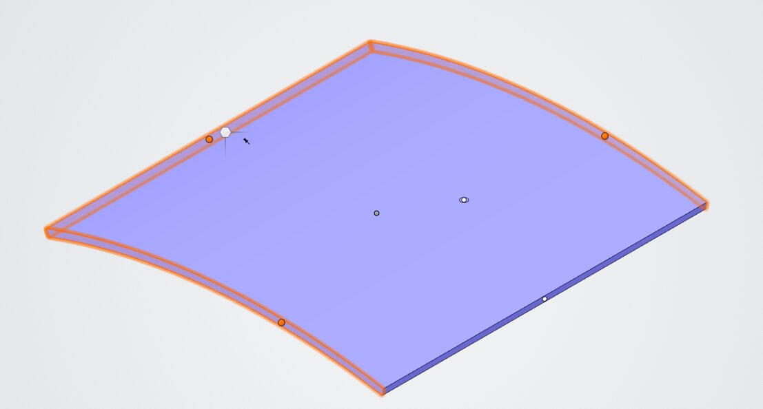
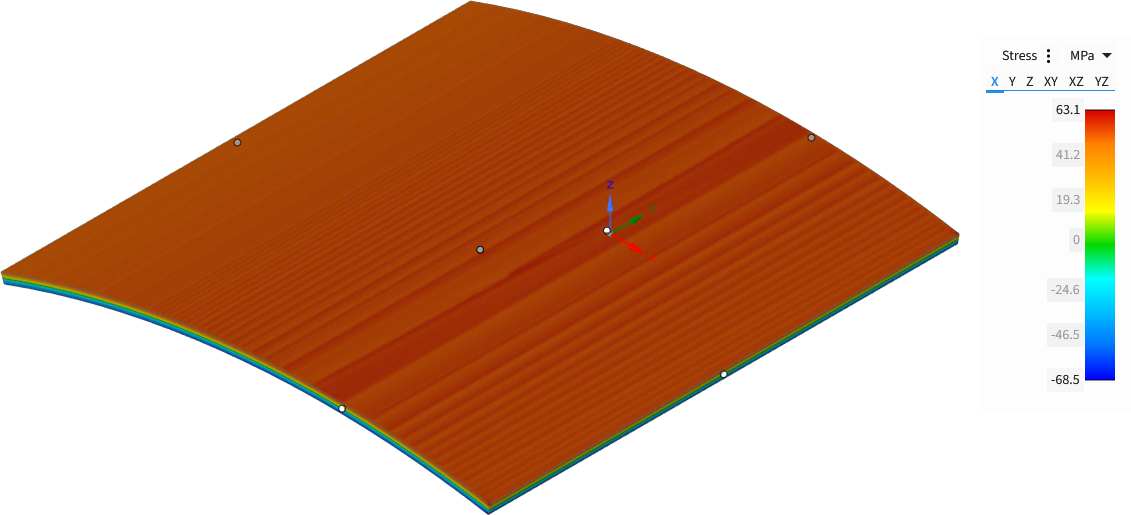
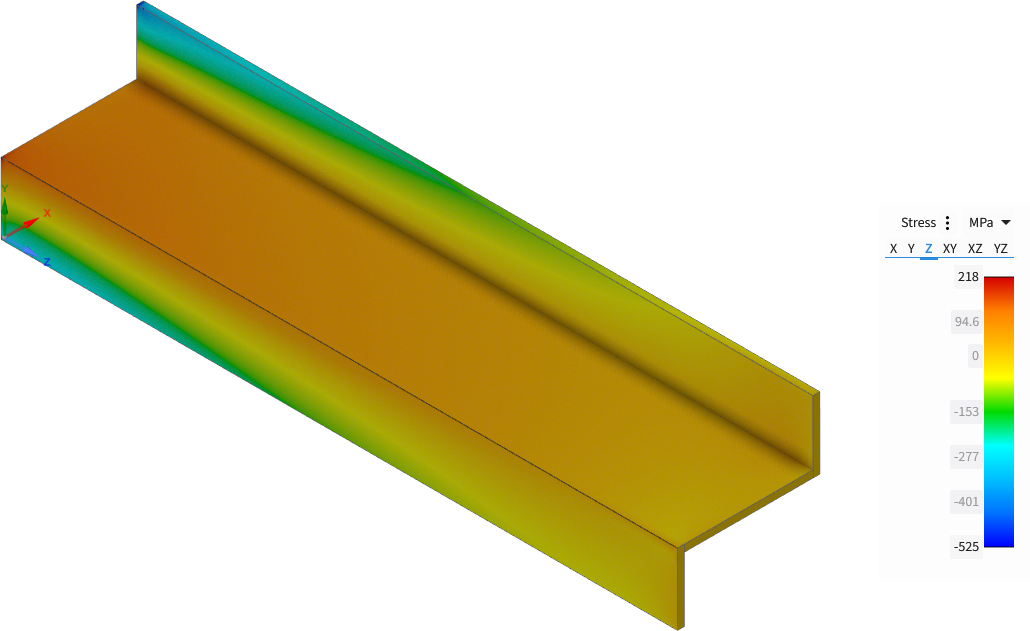
This is the resulting tangential stress distribution across the outer surface for both load cases, produced at high fidelity with the NVIDIA Quadro P4000 GPU.
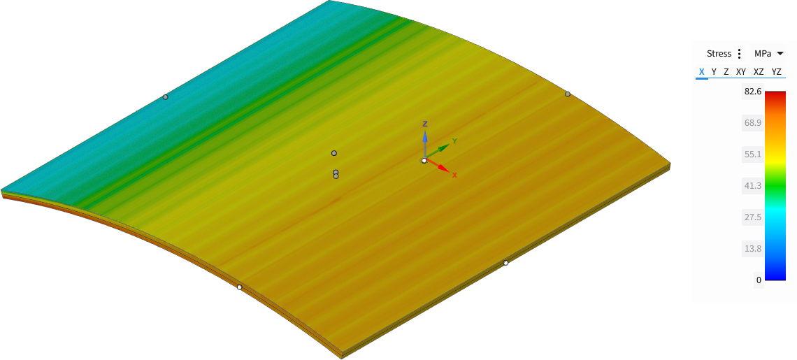
Load Case 1 Tangential Stress Distribution

Load Case 2 Tangential Stress Distribution
In Explore mode, Discovery accurately predicted the tangential stress on the outer surface at point E (indicated by the coordinate system axes) for both load cases. At the higher fidelity settings with the GeForce RTX 4070 GPU, the results were impressively accurate with extremely low error margins.

Load Case 1 Error Margins

Load Case 2 Error Margins
LE5 – Z-Section Cantilever
Next in our NAFEMS benchmarking series we will look at a Z-section cantilever. Cantilever beams are essential elements found in numerous engineering applications, ranging from mechanical equipment like crane booms to civil structures such as balconies and bridges. Z-sections offer notable benefits including enhanced resistance to torsional loads and lateral buckling when compared to simpler open sections.

Z-Section purlins are beams across the length of a roof (Source: BW Industries)
What are the unique features of NAFEMS LE5?
This benchmark investigates the Discovery’s capabilities when modelling cantilever bending under torsional loads. The test model features a Z-shaped cantilever with a length of 10 meters and a cross-sectional thickness of 0.1 meters. One end of the cantilever is fixed, while a torque of 1.2 MN is applied to the other end. With a theoretical reference value of –108 MPa for the axial stress, this benchmark provides a solid benchmark to measure Discovery’s results against.

FEA schematic for LE5, taken from The Standard NAFEMS Benchmarks
How are we setting this up in Discovery Explore?
This benchmark can be modelled in two different ways: either by directly applying a 1.2 MN-m torque boundary condition to the entire end face, or by imposing two 0.6 MN shear loads on the arms of the cantilever.
In both configurations, the cantilever is fixed at one end and remains unconstrained at all other locations. The following images illustrate the Discovery physics tree and show precisely where these boundary conditions are applied in each setup.


LE5 Results in Ansys Discovery
Discovery delivers impressive accuracy on the LE5 benchmark, even at low fidelity. At higher fidelities, the margin of error drops below a single percent.


Direct Torque Approach Results

Shear Load Approach Results
The LE5 NAFEMS benchmark clearly highlights Discovery’s capabilities in handling coupled bending and torsion analysis effectively.
More in this series:
NAFEMS Discovery Benchmark Series – Part 1: Introduction
NAFEMS Discovery Benchmark Series – Part 2: Pressure Plates
NAFEMS Discovery Benchmark Series – Part 4: Axisymmetric Geometries
NAFEMS Discovery Benchmark Series – Part 5: Discovery Scripting (Coming Soon)