
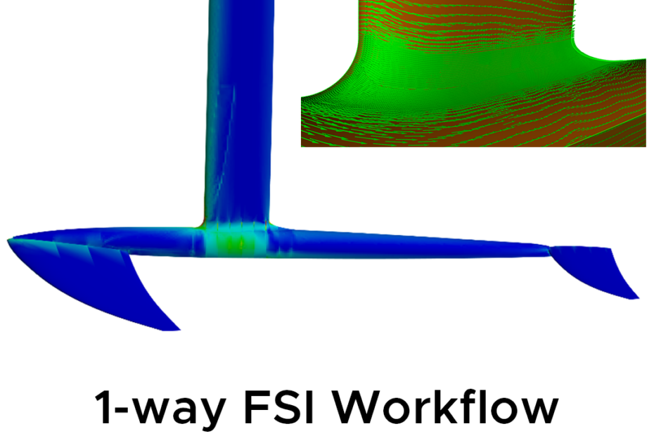
Mapping fluid pressure into a structural model can help engineers assess composite designs without the complexity of a fully coupled simulation. Let’s dive into the workflow and apply it to a hydrofoil example where it adds tremendous value.
When fluid loads act on a structure, engineers may need to understand both the pressure distribution and the structure’s response. A one-way fluid-structure interaction (FSI) workflow connects those analyses: calculate the fluid pressure first, then apply it as a load in your structural model.
The approach is most appropriate when structural deflection is small enough that it does not significantly alter the flow. It does not capture feedback from the deformed shape to the fluid, but it can provide useful structural insight with less complexity than a fully coupled analysis.
From fluid pressure to composite failure results
The process starts with geometry that can support both the fluid and structural analyses. In the example described here, the hydrofoil geometry was built in Ansys Discovery.
An external-flow simulation is run in Discovery’s Explore mode to calculate the pressure acting on the structure’s surface. In Ansys 2026 R1, Explore results can be saved, enabling the pressure data to be brought into Workbench using an External Data system.
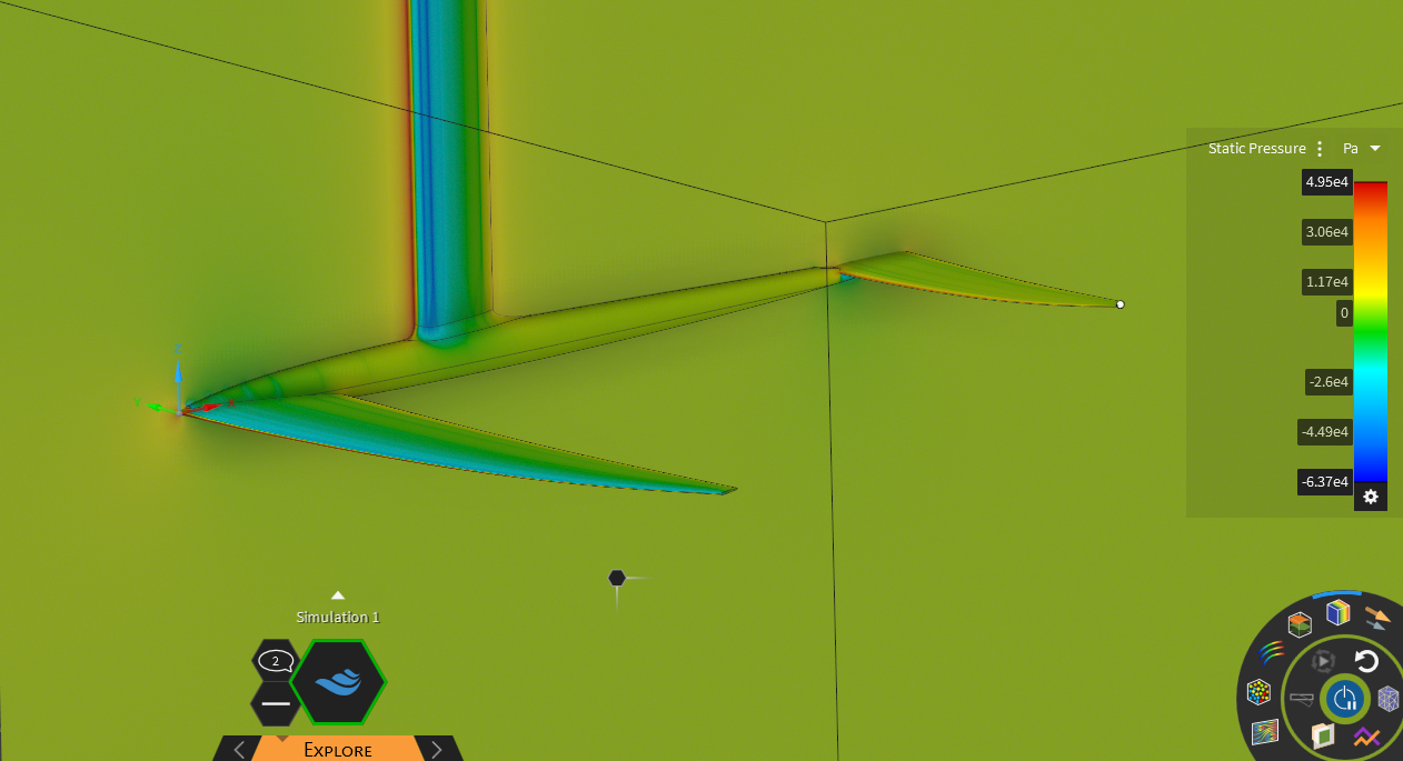
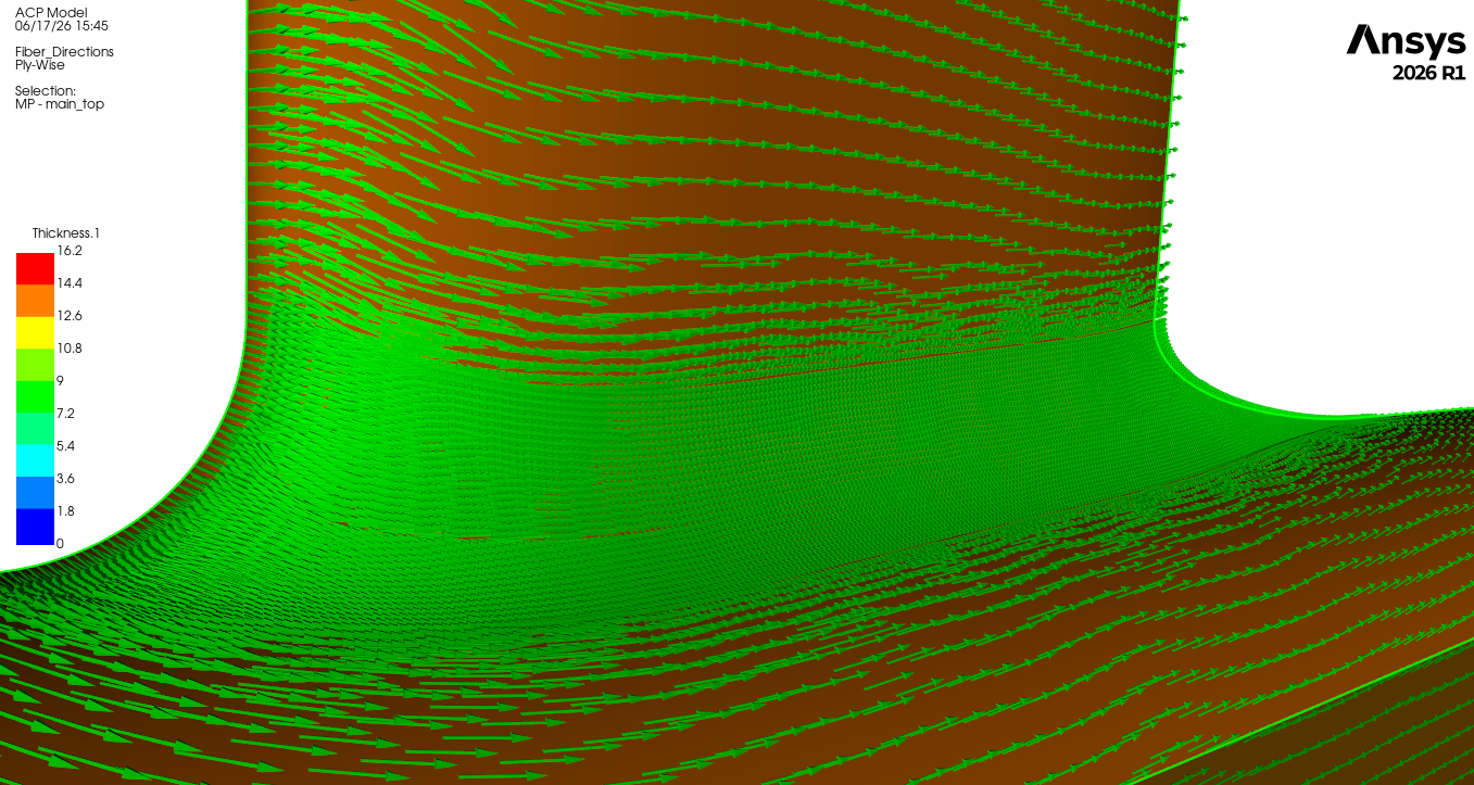
For the structural model, the relevant surfaces are sent to Ansys Composite PrepPost (ACP), where the engineer defines the laminate layup, including the material and orientation of each ply, as well as any core or additional structural features. In the hydrofoil example, the lifting surfaces and mast use sandwich panels, with a core between carbon-fibre layers. Ribs are included to increase stiffness. ACP transfers the layup to Ansys Mechanical as a layered shell model.
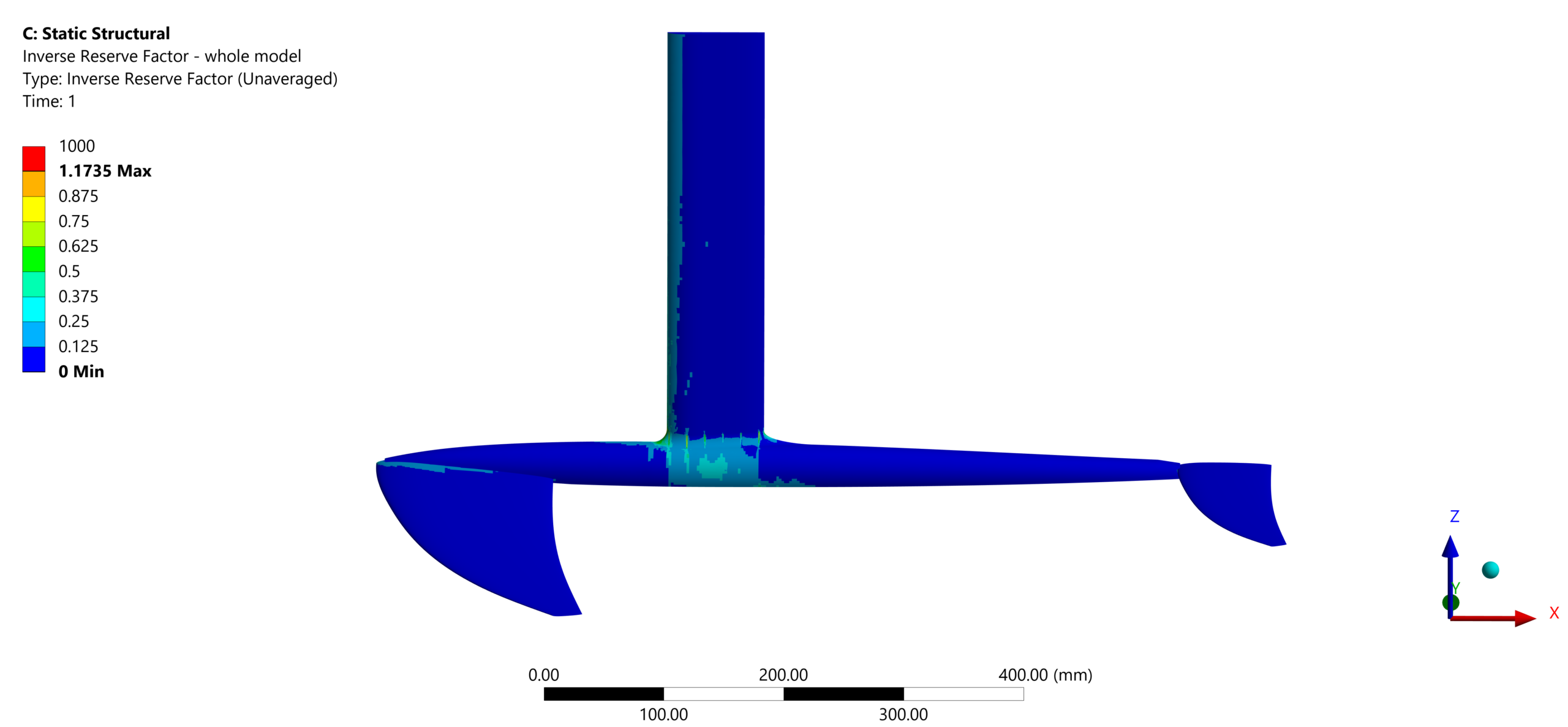
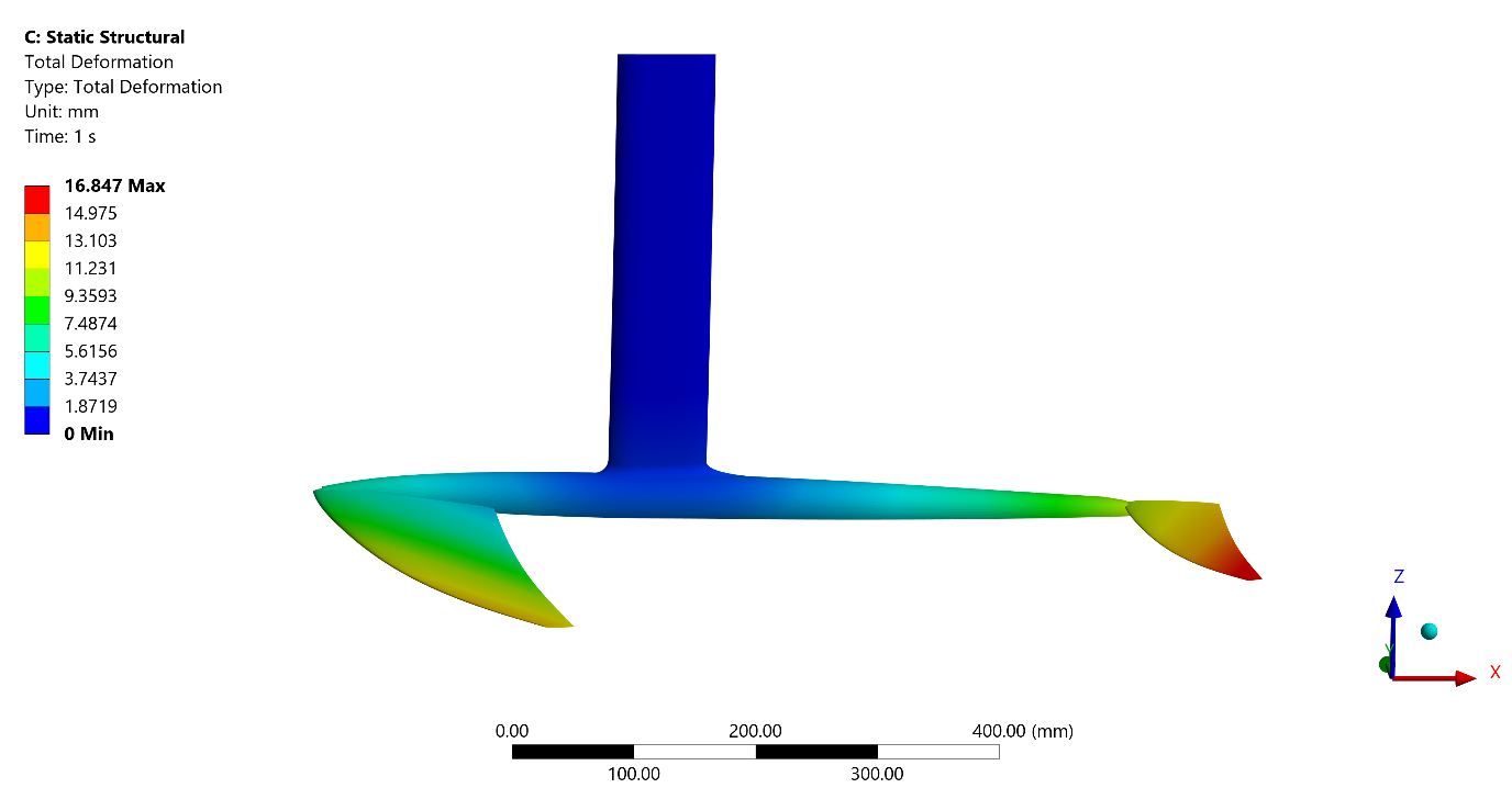
In Mechanical, an Imported Load maps the saved Discovery pressures onto the shell surfaces. The mapped load should be checked to confirm it covers the intended surfaces and represents the expected loading pattern. A static structural analysis then calculates the structure’s response. Composite failure result objects can help identify the ply and failure mode associated with a predicted concern.
This gives the engineer more than an overall deformation or stress picture. The results can help pinpoint where in the laminate a potential issue occurs, providing a more focused basis for design changes—such as adjusting the number or arrangement of plies.
Our key assumption: the flow does not change significantly with hydrofoil deformation
In one-way FSI, the fluid solution is calculated first and is not updated after the structure deforms. The structural analysis assumes that this deformation is too small to materially change the flow or pressure distribution.
That assumption is often reasonable for relatively stiff structures under moderate loads. If deformation changes the shape, twist or angle of attack enough to alter the fluid loads, however, the one-way result may no longer represent the physical behaviour. A two-way FSI approach may then be required.
Why not always use two-way FSI?
A two-way FSI simulation accounts for feedback: fluid pressure deforms the structure, and the changed shape affects the flow and subsequent pressure loads. That can be essential for flexible structures, large deflections and aeroelastic problems, but it comes with additional demands.
The fluid and structural calculations must be coupled, often over many time steps in a transient simulation. This increases computational cost and setup complexity, and can make the analysis more demanding to converge and validate.
For early design exploration, those costs may not be justified if the structure is stiff and its deformation has little effect on the flow. A one-way workflow can provide a more efficient first assessment of structural response, while reserving two-way FSI for cases where the flow-structure feedback is important to the engineering question.
Example: applying this workflow to a hydrofoil
A hydrofoil illustrates how mapped pressure loads can help an engineer understand load paths in a composite structure. In this example, the front wing generates most of the lift. That load travels through the fuselage and into the mast, making the mast-fuselage junction an important region to assess because of its bending and complex stress state.
The workflow brings together an estimated external-flow pressure distribution and a layered-shell structural model. The resulting Mechanical analysis can show how the load is carried and which parts of the laminate may be most affected. The hydrofoil is just one example; the same general method can be applied to other components where fluid pressure acts on a composite structure.
Where the approach can be useful
One-way FSI can be useful in early-stage design work on components such as:
- Hydrofoils, rudders, keels and fins
- Wings, winglets and control surfaces for drones and small aircraft
- Automotive and motorsport aerodynamic parts, including wings, splitters and diffusers
- Wind turbine and fan blades, before a detailed aeroelastic study
For smaller composite manufacturers, the workflow using Ansys Discovery can also make an initial pressure-to-structure investigation more accessible.
Practical considerations and limits
The fluid model’s scope matters. In this example, Discovery does not capture free-surface effects near the waterline, which can significantly affect the loads on a foil operating close to the surface. Predictions involving stall or separated flow may also require a more detailed CFD analysis.
For final sign-off, certification or high-accuracy load prediction, engineers may choose to use Ansys Fluent with an appropriately resolved mesh, then map the resulting pressures into Mechanical. If structural movement significantly changes the flow, a transient two-way FSI analysis may be necessary.
Using these results to guide design changes
Once the structural model is set up, engineers can use the results to compare laminate choices. A design of experiments (DOE) can vary layup parameters and help reveal which choices have the greatest effect on stiffness or failure predictions. Those findings can inform trade-offs involving mass, cost and structural performance.
The value of this 1-way FSI approach is that, when its assumptions are valid, it is a quick and convenient way to connect a fluid pressure field to composite structural behaviour —helping engineers examine load paths, identify critical plies and explore design options without taking on the additional computational and workflow demands of a fully coupled simulation.