
Part 3 – Guest Blog by Julio Martins, former Aerodynamics & Cooling Lead, UNSW Redback Racing
(Revisit Part 1 here – A look back at Redback Racing FSAE Aerodynamics Strategies)
(Revisit Part 2 here – Refinement and Characterisation of RB24: A Full Understanding of the Aerodynamics Package)
The flow structures and overall flow “cleanliness” improved considerably from RB23 to RB24, especially in the undertray/side aero region as well as the front wing. Performance gains were achieved on the rear wing using a curved mainplane to have a higher effective angle of attack in the outboard regions of the rear wing where flow is the cleanest however majority of the flow improvements were seen in the front wing and undertray.
We will begin with the flow underneath the cars and the improvements in the undertray design from RB23 to RB24 by looking at both streamline visualisations and velocity vector plots of the flow between the ground and undertray as well as using animations of velocity vectors in the side aero/venturi tunnel region.
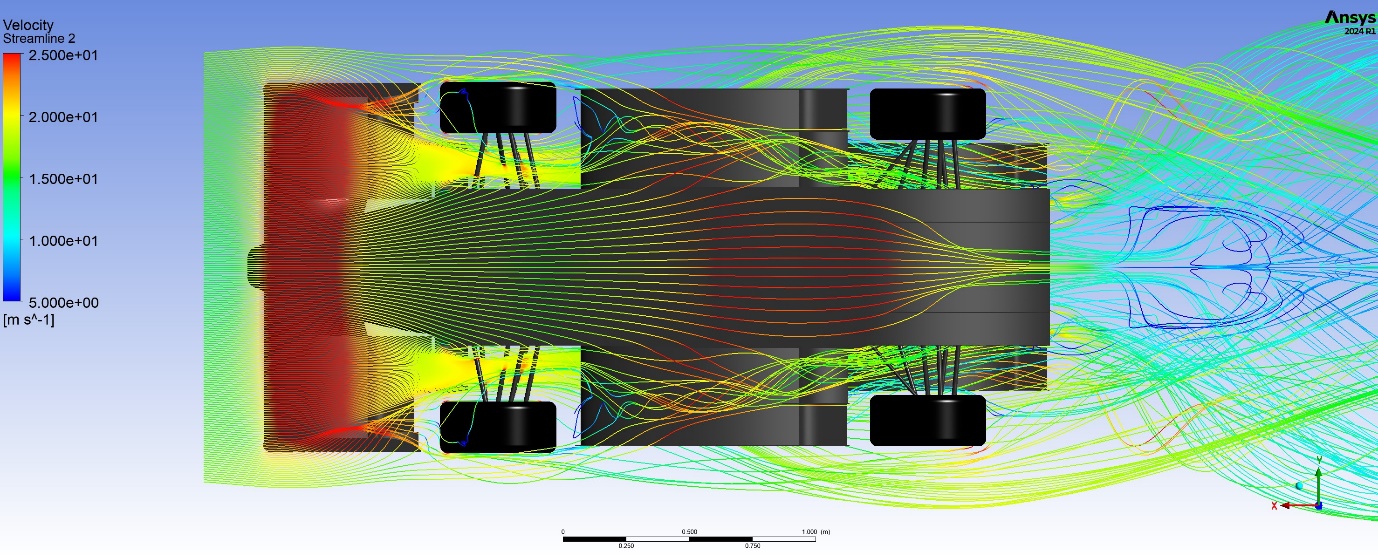
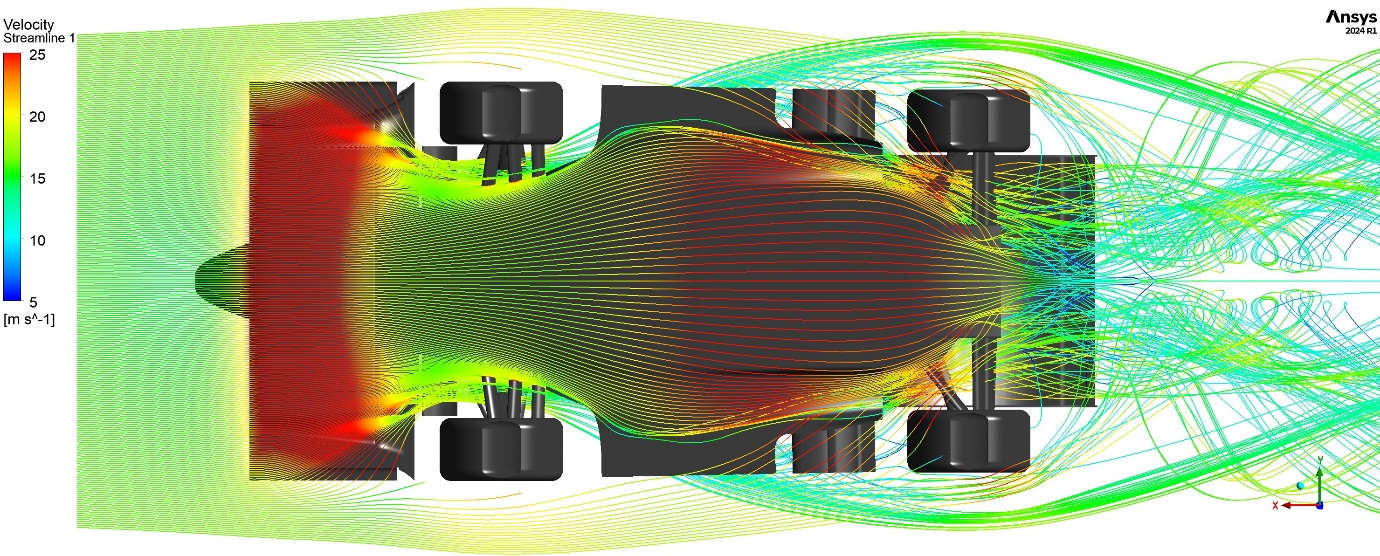
Streamline Illustrations of Undertray Flow on RB23 (Top) and RB24 (Bottom)
It can be seen from the streamline visualisations of RB23 and RB24 above that the flow on the underside of the car is improved in RB24 with much less vorticity and turbulence than in RB23. This is especially noticeable in the side aero (outboard) region of the undertray where the flow in the side venturi tunnels of RB24 is much cleaner than the flow underneath the side wing stacks of RB23. It can also be seen that the central diffuser of RB24 is much more effective than on RB23 where RB23’s diffuser, although larger, was seen to have a substantial amount of stall. This diffuser stall is more easily seen in the velocity vector plots of the underside flow below and similarly shows the vorticity in the side aero region on RB23 and lack thereof on RB24.
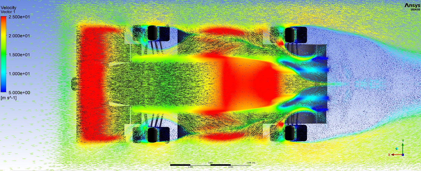
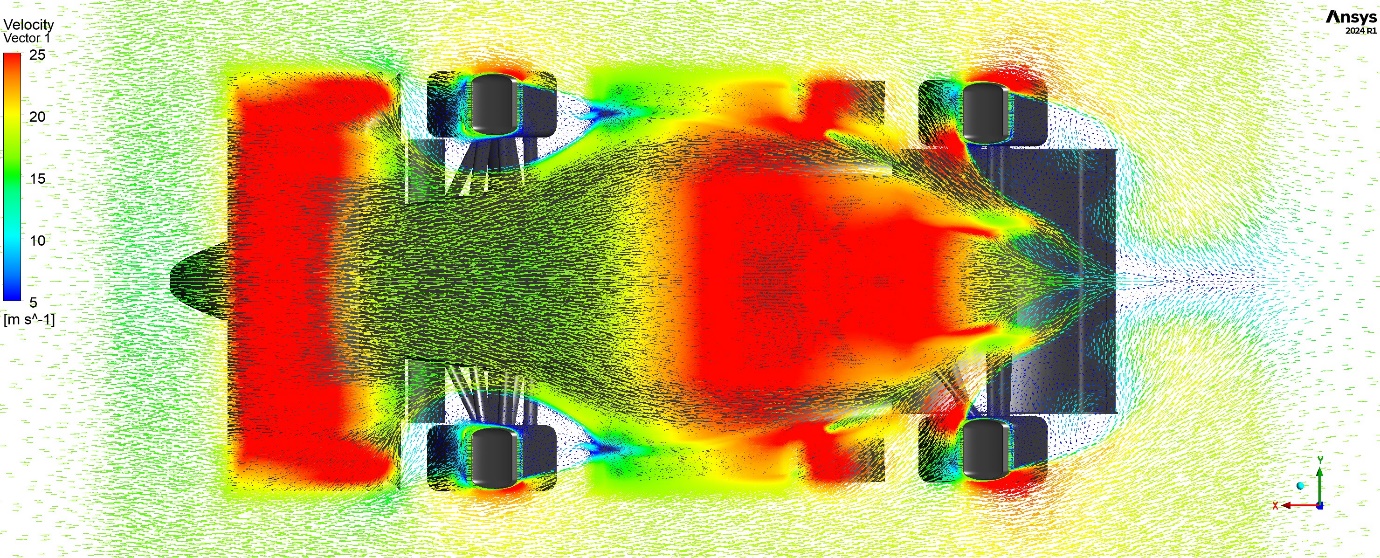
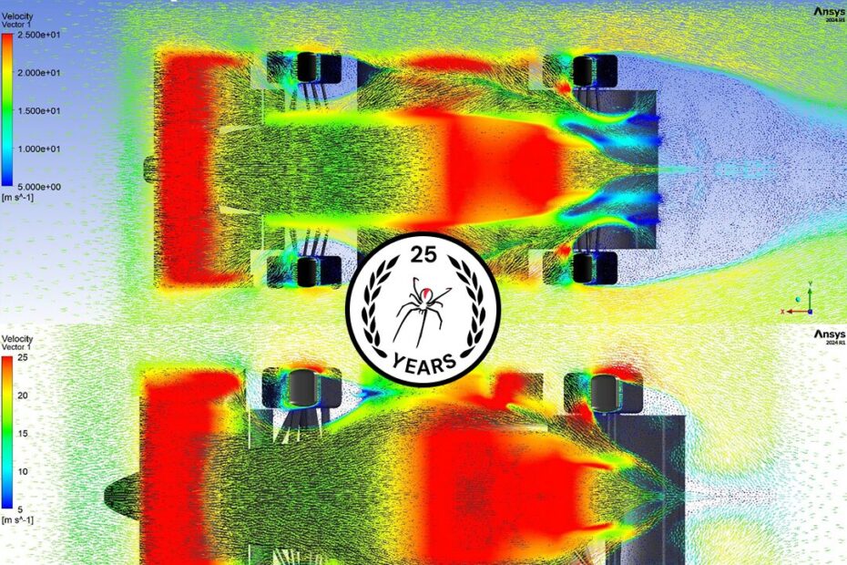
Velocity Vector Plots of Undertray Flow on RB23 (Top) and RB24 (Bottom)
Further detail in the flow around the side aero/venturi tunnel regions and front wing can be seen in the video sequence below:
Animations of Side Region Flow and Outbound Front Wing on RB23 (Left) and RB24 (Right)
In the video, the visualisations help show how the performance of the front wing has been improved using flow control strategies that utilise vortex induced downforce underneath the endplates of RB24’s front wing. This flow control and vortex manipulation helped to manage front wheel wake by reducing the amount of high energy flow impinging on the front tyre surface. This subsequently reduced the front tyre squirt which becomes beneficial to undertray performance as well as improved flow quality further downstream, behind the front wheel (as seen in the visualisation of the side region flow).
Take note of the reduction in downturned flow by the front tyre on RB24 compared to RB23 and resulting reduced tyre squirt. Also take note of the vortex behaviour of the flow coming under the endplate and rolling up below the “outboard diffuser” section of the front wing as we call it. This outboard diffuser section allows the vortex to grow in strength underneath the main element section to improve downforce generation while the 2nd and 3rd curved elements work to expand the vortex core so that the outside high energy flow of the vortex is thrown outboard or over the top of the front wheel while the low energy vortex core is expanded onto the tyre face. There is also reduced vorticity off the top of the vertical endplate on the front wing of RB24 compared to RB23 using the 3D twisted airfoil shaped vertical endplate on RB24 compared to the prismatic endplate on RB23. The endplate on RB24 is also disconnected from the successive elements of the wing to allow flow to pass between it and the curved elements of the outboard diffuser section to further reduce vorticity.
Overall, our extensive use of CFD simulations has provided us with insights that have significantly improved the flow quality around RB24 (compared to RB23). This outcome was both a culmination of the improvements in aerodynamic design and understanding and growth in manufacturing techniques and composite knowledge over the past few years. The growth of these two intrinsically tied departments has allowed for the more complex geometries and more efficient aerodynamic features to become a reality.
Conclusion
Over the past 3 years, the team has seen a tremendous growth in aerodynamic knowledge which is evident in the evolution of the aerodynamic designs since RB21. This aerodynamic growth has been coupled with an equivalent growth in composite knowledge which has allowed for the improved aerodynamic designs to become reality. This series has focused primarily on the aerodynamic advancements, especially in CFD simulation and aerodynamic behaviour in the context of vehicle dynamics. There is no doubt that LEAP Australia and the access they provide to industry leading tools like Ansys has enabled us to grow our knowledge and skills and none of the improvements we have made would have been possible without them. I am incredibly thankful for this opportunity to share what I, and so many others, have been able to learn and achieve because of LEAP Australia’s support. We look forward for the future to come!
I hope other students and FSAE teams can further grow their knowledge and understanding through this blog and think of even more ways to analyse the results and draw useful conclusions from all the data that CFD can provide. Best of luck and happy simulating!