Figure 1: Interceptor aircraft created in Part 2 of this series upon successful interception of the target aircraft
This Time – Communication via LEO Constellation
Lastly, the DRM is expanded to incorporate a communications relay from the intercept aircraft to a ground facility near the east coast of Australia. This link is facilitated via a phased array mounted on top of the aircraft and a LEO constellation which serves as a relay between the aircraft transmitter and ground facility receiver. The goal here is to evaluate the access intervals between assets and ensure that regardless of the intercept route taken, the aircraft can maintain a satisfactory communication link to the ground facility.

Figure 2 Phased array onboard intercept aircraft tasked with communications to LEO constellation
LEO Constellation
The LEO constellation is arranged in a Delta 45.0: 12/6/1 walker configuration, using the “Walker” tool within STK. This produces a 12-satellite constellation, with six orbital planes, each at an inclination of 45 degrees.
Each of the satellites possesses a transmitter and receiver. These are set up in a linked fashion, such that any change made to the definition of these communication objects will carry across the entire constellation. Whilst this constellation remains quite sparse, this linked setup enables the straightforward scaling of the constellation to much larger configurations, without drastically increasing user setup time.

Figure 3: Overview of LEO Constellation orbit paths, shown here in light blue
Chain Access
To enable communication via the LEO constellation, a chain object is defined within STK. This allows the user to define a start and end point to the communication chain, as well as any intermediary jumps in between. The chain is setup up to allow the signal to travel from the aircraft to a LEO satellite. From here, it can either be broadcast straight to the ground facility, if line-of-sight access is available, or relayed to a second LEO satellite and then down to the facility.
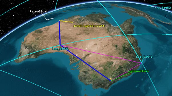
As expected, this generates several simultaneous links at any given time, even with the sparse 12 satellite constellation used in this DRM. Fortunately, STK’s latest release allows for the computation of an “optimal strand.” In this instance, the optimal strand is computed based on minimal distance the signal must travel, however it could be computed based on processing delay, or some custom user scalar instead. Figure 4 and Figure 5 show an example of the optimal strand updating as time progresses. In Figure 4, the signal recognises the shortest transmission path is via Leo_Sat43, however 3 minutes later, as this satellite passes further south in its orbit, the optimal strand updates to reroute via Leo_Sat21 instead.

Figure 4: LEO Constellation and communication chain. Optimal strand highlighted in blue via LEO_Sat43. Other available strands shown with pink line.

Figure 5: LEO Constellation and communication chain. Optimal strand highlighted in blue now via Leo_Sat21. Other available strands shown with pink line.
Communication Results
With the access chain established, we can start to integrate both the duration of access between assets, and the quality of this access as well. Below, Figure 6 shows the timeline elements generated in STK which provide the first indication of communications availability. Here the top orange bar shows the availability of the aircraft itself, I.E. time between take-off and landing. Beneath it, the segmented orange bars show the times during which a complete chain access is available from the aircraft through the LEO constellation and back to the east coast ground facility.

Figure 6: Timeline elements within STK provide the first indication of access duration and gaps in the created chain object.
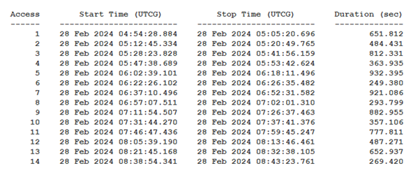
These results can also be expressed in more detailed reports and graphed. Here, Figure 7 shows a complete chain access report, providing information about each period during which the full communication chain is present.

Figure 7: Screenshot of the complete chain access report generated in STK. Not pictured: the summative information about the chain including total combined access duration.
Once again, these results can be compared against design requirements and desired mission outcomes. Crucially the user is now free to explore various edge cases and contingency plans. For example, if a particular satellite were to become unavailable during the mission, is there sufficient redundancy built into the system such that it can maintain mission operability, or does the system require additional backups prior to real-world deployment. Being able to explore these questions in a single physics accurate simulation serves to greatly reduce risk and increase operational preparedness much earlier than tradition segmented engineering workflows.
For more DRMs on communication with STK, including detailed link budget reports, see our other entries in this series here:
Conclusion
Recall the initial goal of this DRM – to create a physics accurate model to analyse the performance of a radar detection system, and the subsequent response of airborne assets. In only a few steps we have created a multi-domain simulation, capable of visualisation and analysis of this interconnected system. Any change made to an individual asset will immediately reveal its impact on the bigger mission. In turn, this DRM can now grow and evolve throughout the entire engineering process. As more detail on the project becomes known the DRM can grow alongside in simulation fidelity and analysis detail. From initial concept work to design optimisation and right through to deployment the DRM now represents a single unified solution for an otherwise complex real-world problem.
More like this
For more information on Digital Mission Engineering, the many other applications and industries for Ansys STK, and guest Blogs from in-industry users, be sure to check out the Leap Digital Mission Engineering page.

